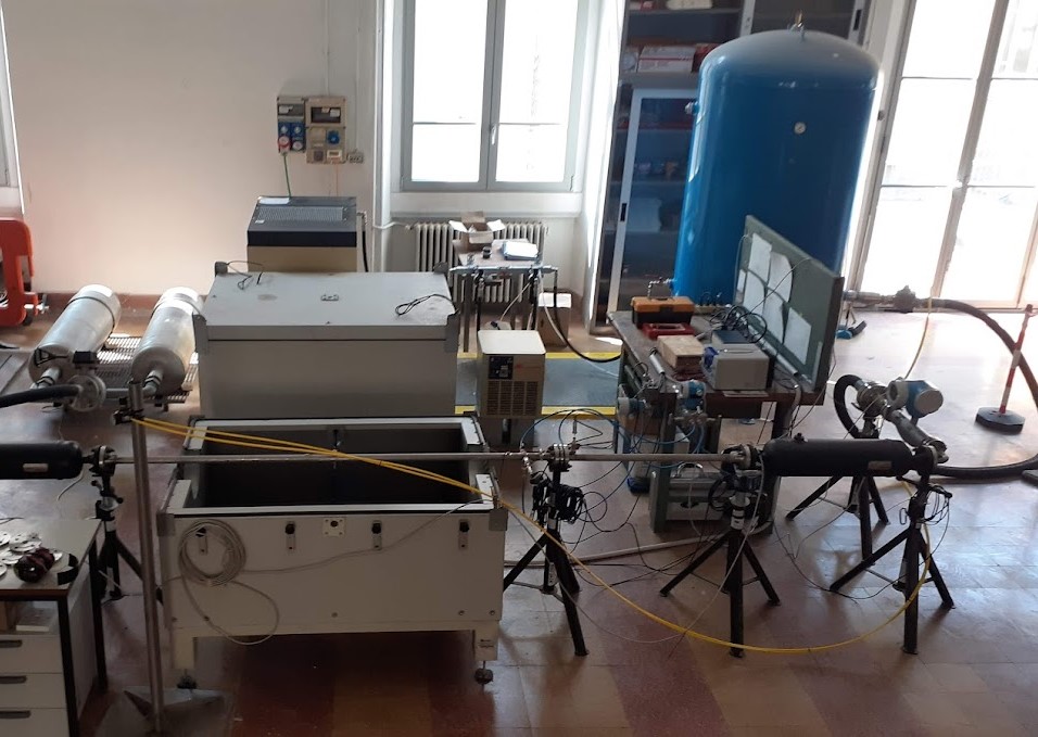
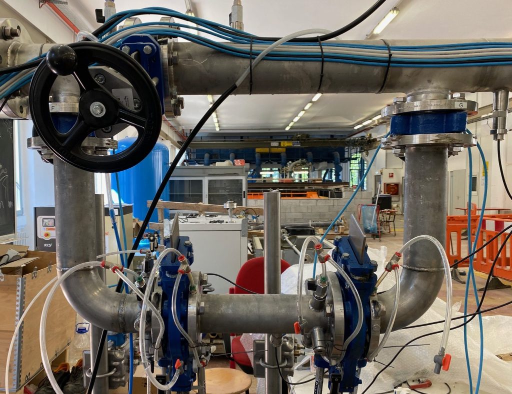
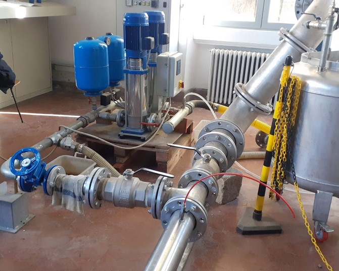
The following experimental facilities are located at the Hydraulic laboratory of Politecnico di Milano (Fantoli)
E-NET (download the inp file for Epanet and contact us)

An experimental distribution network developed with the support and collaboration of A2A Ciclo Idrico, based on the benchmark network proposed by Jowitt and Xu [1], used in more than 50 scientific publications for optimizing various aspects of a water distribution network, such as leakage reduction, valve placement, and energy recovery.
Goals:
• Be able to simulate a realistic water supply network;
• Experimentally verify the effectiveness of specific management strategies;
• Experimentally verify calibration procedures and optimization algorithm effectiveness;
• Test new technologies in a realistic context (TRL6) (valves, leak detection systems, energy recovery, control systems, reducers, meters, data management systems);
• Test AI methods for leak localization and other network optimization approaches;
• Provide an effectiveness technology tranfer hub for sudents, professional and technical staff.
With the advantage of reducing the cost of technological/modeling/management field tests and evaluating their effectiveness in a controlled environment such as a laboratory.
Main characteristics:
- 3 inverter driven pumps
- Diameter : 25 – 100 mm
- Roughness : 150
- Demand : 0-7 (L/s)
- Emitter coeff: 0.0008-0.008
- Total length : 1.1 km
E-Loop

Hydraulic devices test loop under standard and critical operation conditions.
Performances parameters defined by the standard can be evaluated: IEC 60534, IEC 60193, ISA 72 01 01.
Main characteristics:
- Test line diameter: 25-150 mm
- Multistage pump (135 KW)
- Measurements: pressure, flowrate, temperature, acceleration, solid particle concentrtion
- Maximum flowrate 35 l/s
- Maximum pressure 25barg
- Critical conditions: cavitation /erosion
Air-Loop
Plant to test flow control devices using dry air as a working fluid. Both fluid-dynamic and acoustic performances of the tested devices can be obtained as specified by the standard IEC 60534.
Main characteristics:
- Pipeline diameter: 25 mm
- Anechoic chamber
- Measurements: static pressure, mass flowrate, temperature, wall pipe pressure fluctuations, free-field acoustic pressure
- DN15 Coriolis flowmeter (accuracy 0.1%)
- Maximum inlet pressure: 10 barA
D.I.T. (Direct Impact Test)
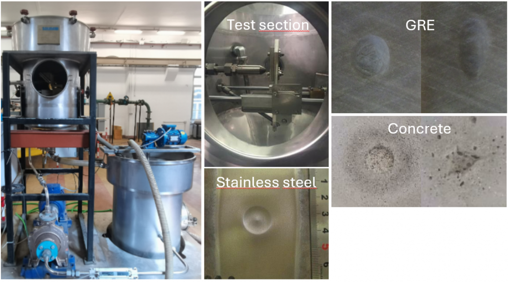
Particle erosion test plant, to characterize the resistance of materials to erosion by a particle-laden flow.
Main technical features:
- Nozzle exit diameter ≈ 8 mm
- Maximum jet velocity at nozzle exit ≈ 35 m/s
- Solid concentration ≈ 1% by volume
- Measured quantities: pressure upstream of the nozzle inlet, flowrate, mass of sample before and after the test
LowRe-Loop
Low Reynolds Number tests loop. As operating fluid we use a variable mixture of water and glycerine (viscosity 40-60cSt) to provide test of hydraulic devices under low Reynolds number conditions.
Main characteristics:
- Pipeline diameter: 80 mm
- Measurements: density, pressure, flowrate, temperature
- DN80 Coriolis flowmeter (accuracy 0.1%)
- Maximum flowrate 22 l/s
- Maximum pressure 1.8 barg
Cavitation Plant
Hydraulic devices test plant under standard and cavitating conditions.
Main charachteristics:
- Diameter 25-100 mm
- Measurements: pressure, flowrate, temperature, acceleration, rpm, brake force
- Maximum flowrate 60 l/s
- Maximum inlet pressure 10 barg
- Minimum outlet pressure -0.5 barg